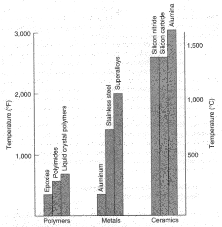
Certain applications involving high temperatures has driven the development of ceramics and ceramic matrix composites (CMC). An illustrative comparison of service temperature limits of ceramics, polymers and metals are shown in figure 2.1.
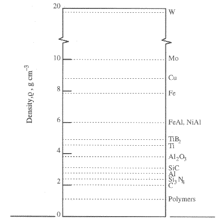
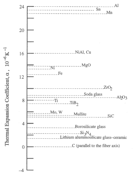
The characteristics of low density and low thermal expansion of ceramics ass8ume a great deal of importance in most applications. And that is shown in figures 2.2 and 2.3. respectively.
Besides these favorable characteristics, ceramics also have some unfavorable characteristics listed below:
continuos fiber ( can be woven, braided and etc.)
small diameter, <20mm (depends on application)
high strength (2068 Mpa tensile strength in air and other hostile environments)
creep resistance
High elastic modulus, >45MPa
The introduction of the energy-dissipating mechanisms is the main goal in the development of ceramic composites.
The presence of particulates, whiskers or continuos fibers enhances toughness by at least three mechanisms:
deflection of the propagating crack tip
energy absorption by pull out of the fibers.
bridging of the crack
(holding the two faces of the crack togetter)
Thus ceramic material shows a damage-tolerant behaviour.
Common ceramic matrix materials include various glasses, glass-ceramics and ceramics, such as carbon, silicon carbide, silicon nitride, aluminides and oxides.
The ratio of modulus of reinforcement and the matrix is very low for ceramic compositesand can frequently be equal to unity or even less.This ratio for the polymer or metal matrix is typically between 10 to 100. The high modulus ratio in polymer and metal matrix composites allows an efficient load transfer from the matrix to the fiber by means of the strong interface. However in a CMC, the low modulus ratio means that the reinforcement and the matrix are not much different in their load-bearing capacity.
Thus potential advantageous of fiber-reinforced ceramic composites are as follows:
- High strength and strength-to-density ratio
- High strength at high temperatures
- Low density
- High stiffness to density ratio
- Toughness (impact and thermal shock)
- Improved fatigue strength
- Improved creep strength
- Controlled thermal expansion and conductivity
- Improved hardness and erosion resistance
- ability to tailor properties for end-use specification.
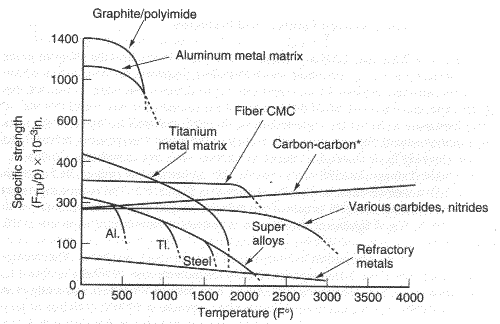
Fig. 2.6. Spesific strength comparisons of advanced materials
2.3 APPLICATIONS OF CERAMIC MATRIX COMPOSITES:
Ceramic components can be introduced into automobiles. The most important resultant gain would be a reduction in fuel consumption because of the light weight nature of ceramics and CMCs.
Heat exchangers represent an area of application where ceramics or CMCs can be cost-effective because of their high-temperature capability. One can use the waste heat from the furnace exhaust to preheat the inlet combustion air and thus save fuel consumption. Such heat exchangers can be used in industrial furnaces, gas turbines and fluidized bed combustion units. Ceramics and CMCs can also result in fuel efficiency in heat engines because of higher operating temperatures, and reduction or elimination of cooling systems.
Because of their light weight with high strength at high temperatures, they are used in aerospace and military applications.
Because of their corrosion resistance and ability to operate with little lubrication. They are used in bearings in missiles.
Other applications include wear parts, such as seals, nozzles, pads, liners, grinding wheels, brakes, etc. For instance, carbon fiber reinforced carbon composites are being used in aircraft brakes.
They are also used in dies and tool bits, medical implants and land-based power and transport engines.
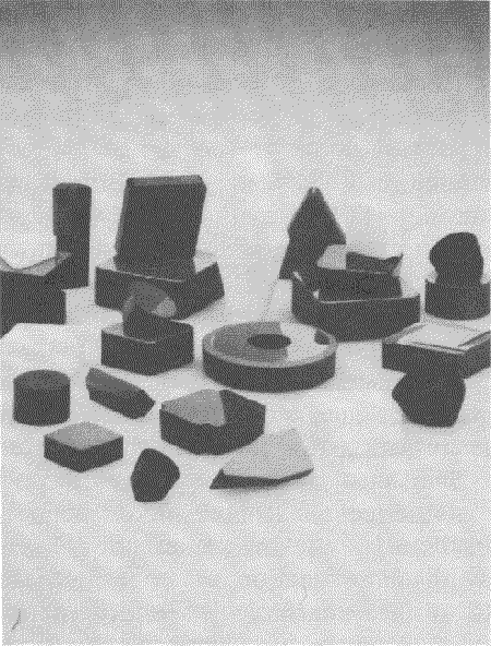
Fig. 2.5. Ceramic and ceramic composite cutting tool inserts (by courtesy of Greenleaf Corporation, Saegertown PA, USA).
2.4.PROCESSING OF CERAMIC MATRIX COMPOSITES:
The goal of production processes for ceramic composites is to produce materials with a predetermined microstructural geometry with a minimum of harmfull defects.
For the preparation of particulate and whisker reinforced composites, processing techniques for traditional ceramics with some modifications are utilized.
For long fiber composites special new techniques had to be developed , because continous fibre geometries have to be preserved with minimum fiber damage and many fibers degrade at the temperatures required for sintering of ceramics.
The most impotant factor that has to be considered in all composite processing is to optimize the strength of the fiber/matrix interface since this has a critical influence on properties.
Processing methods used for conventional ceramics will be discussed firstly, as a basis for descriptions of the processing of particulate composites and to understand the difficulties encountered with long-fiber composites.
2.4.1 Processing of traditional ceramics and particulate composites:
The basic steps in the preparation of ceramic components by established powder processing are:
- The starting material, generally in powder form, is prepared.
- The powder is formed into a desired shape, which is called green body.
- The green body is sintered at a high temperature to obtain a sufficiently dense material.
- The sintered compact is finished into the final shape.
Some examples of powder processing routes are shown in figure 2.7.
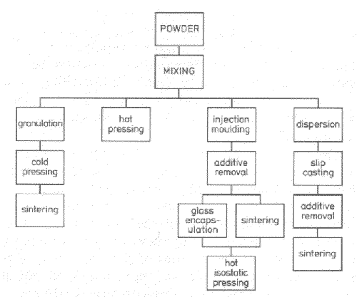
Fig. 2.7. Some examples of powder processing routes.
Powder forming processing has two functions:
- To shape the powder as nearly as possible into the shape of the component
- To bring the powder particles as closely as possible to permit effective sintering.
In cold forming processes the powder is formed into a green body prior to subsequent sintering. However, in hot forming processes forming and sintering occur simultaneously.
The effectiveness of the sintering of the green body is favored by high green density and uniformity of the distribution of the powder particles.
The control and retention of the shape are also favored by a high green density which implies low shrinkage and controllable variation of green body density within the compact.
The principal cold forming processes are:
- uniaxial pressing
- cold isostatic pressing
- slip casting
- injection molding
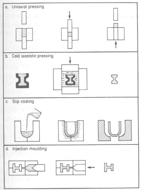
Fig. 2.8. Thermal expansion coefficient of some materials
The choice of method is determined by the geometry, the complexity of shape and the production volume of the component.
- Uniaxial pressing: In uniaxial cold pressing, the powder is poured into a rigid die and then pressed with a closely fitting punch. After pressing the punch is removed and the green compact is removed usually by ejection with a lower punch.
Friction between the powder particles and between the powder and die/punches lead to an uneven distribution of stress throughout the compact This leads to non-uniformity of density and also to variation of elastic relaxation upon unloading which results in the fracture of the compact and this limits the pressures that can be used to about 50 Mpa.
Uniaxial pressing becomes difficult if the fiber contains whiskers or short fibers since the random packing density of particles with fibrous shape is very poor. If the fibers are not to become crushed, the achievable green density is very poor.Moreover, elastic spring-back effects are large.
The shape and the size of the compact is limited by the frictio effects and that it has to be ejected from the die. Thus, the method is suitable for small components with relatively simple geometry.
Since the process is costly, it is suitable for production of large series.
- Cold Isostatic Pressing: In this process the powder is filled into a flexable mold generally prepared from rubber and then subjected to isostatic pressure via a fluid in a pressure chamber.
Friction effects are much less in this process than in uniaxial pressing and the pressing of larger more complex shapes is possible.
The rubber moulds rae relatively easy to produce but the process cycle itself is slow and so the method is appropriate for small series of components.
- Slip Casting: The principle of slip casting is that a slurry of the powder is poured into a porous mould, usually made of gypsum, which absorbs the liquid carrier causing the powder to be drawn to the mould walls.
This method is mostly used for production of traditional ceramics and is ideal for preparation of large, thin-walled, hollow components.
Recent developments in powder preparation have extended its use to advanced ceramics.
For optimum casting, the slurry or slip should be a stable suspension with as high solid contend as possible but with low viscosity.
A process related to slip casting is tape casting in which thin layers of slurry are cast onto a substrate of thin plastic film.
Both slip casting and tape casting are suitable for short-fiber composites, tending to produce a two-dimensionally random fiber orientation.
- Injection molding: Injection molding involves mixing of the ceramic powder with a sufficient amount of polymer or other soft binder to produce a moldable dough. This is then injected under pressure into a mold.
With appropriate flow properties and strength, the mix can be molded to complex and intricate shapes.
It is desirable to produce mixes with as high ceramic powder contend as possible in order to minimise the subsequent binder removal that is necessary to achieve a high green density. However, the powder content is limited to a critical volume fraction above which the viscosity of the mix increases sharply. The limit is set approximately by the point at which particles begin to develop skeletal contact and thus the process is very sensitive to particle shape and particle size distribution.
Injection molding has the potential for the fabrication of short-fiber reinforced composites.
Particular interest is the possibility of controlling fiber orientation through control of the flow of the mix trough the mold.The main problem is the limit to fiber fraction set by packing geometry.
Injection molding is used mostly in the production of large series of components with complex shape. A related process, extrusion is suitable for producing rod and strip with constant cross-sections.
After these cold forming processes, sintering is applied as said before. The basic process is pressureless, solid state sintering. Some modifications such as pressure assisted sintering, liquid phase sintering and reaction bonding have been developed to accelerate the densification and above all to reduce the necessary temperature.
2.4.2 Processing of whisker and short fiber reinforced composites:
Whisker and short fiber composites are difficult to produce using conventional cold formin techniques followed by pressureless sintering. The main source of difficulty is the poor packing characteristics of particles with high aspect ratio.
However, these composites can be prepared using conventional processing with relatively straightforward modifications provided pressure assisted sintering methods such as hot pressing.
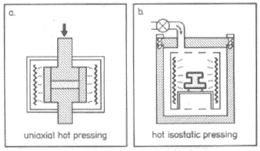
Fig. 2.9. Schematic illustrations of (a) uniaxial hot press, (b) hot isostatic press.
Processing of these composites includes following stages:
- whisker cleaning to remove impurities
- wet mixing of matrix powder and whiskers
- sintering (hot pressing); i.e. uniaxial hot pressing is the most common method in the commercial production of cutting tools.
There are also alternative methods in research such as injection molding and slip casting in association with hot isostatic pressing. Some reported examples are:
cold isostatic + sintering to closed porosity + post HIP
cold isostatic pressing or slip casting + HIP
injection molding + HIP
slip casting + HIP
slip casting +reaction bonding
An example is given in the figure below:
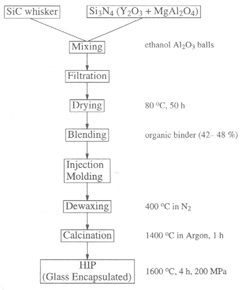
Fig. 2.10. Flow diagram of fabrication of SiCw/Si3N4
The sinter/HIP approach has so far only been possible with low whisker contents since more content results in further shrinkage and with low whisker content it is may not be possible to obtain enough toughness and strength.
Producing complex components with for example slip casting or injection molding introduces special problems associated with variation of whisker orientation in the component which results in variations in shrinkage during sintering leading to distortion in the component.
An example is shown in figure 2.11.

Fig. 2.11. Source of Shrinkage during sintering of injection moulded, whisker reinforced composite.
Another problem associated with small-diameter whiskers is a potential health hazard like asbestos. This necessitates the added expense of special handling facilities. However, the fully sintered materials are unlikely to be hazardous.
2.4.3 Processing of long fiber composites:
These composites can be divided into two as follows:
- Composites prepared by impregnation of a continuos, multifilament yarn of fibers with matrix (most commonly in the form of a powder slurry). The impregnated yarn can be laid up into various geometries prior to consolidation.
- Composites prepared by infiltration of a fiber preform of predetermined shape and usually with a multiaxial fiber geometry.
An underlying principle of techniques developed for long-fiber composites is that a preform of fibers with the required geometry is infiltrated with the matrix or a matrix precursorThe infiltrating matrix can for example take the form of a powder slurry(slurry infiltration), a liquid solution (liquid infiltration), or a mixture of gases or vapors that react to form the matrix.(chemical vapor infiltration, CVI)
Hot Pressing Slurry Infiltration:
The following two-steps need to be considered in the slurry infiltration method.
- The reinforcing fibers are incorporated into an unconsolidated matrix.
- The composite is consolidated by hot pressing.
A schematic of the slurry infiltration method of making a fiber-reinforced glass and glass-ceramic composite is presented in figure 2.12.
The microstructure of the cross section of a unidirectional alumina fiber/glass matrix composite made by slurry infiltration is shown below in figure 2.13. The associated pressure temperature schedules are also presented in figure 2.14.
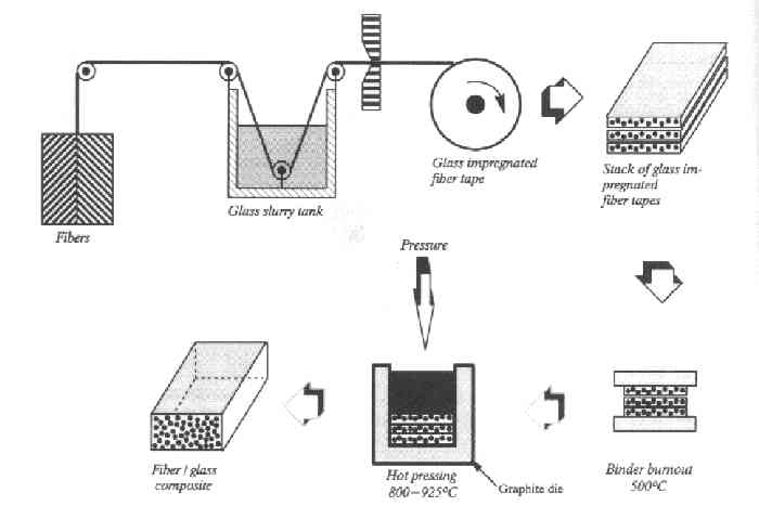
Fig. 2.12. A schematic of the slurry infiltration process of making a fiber-reinforcedglass and glass-ceramic composite.
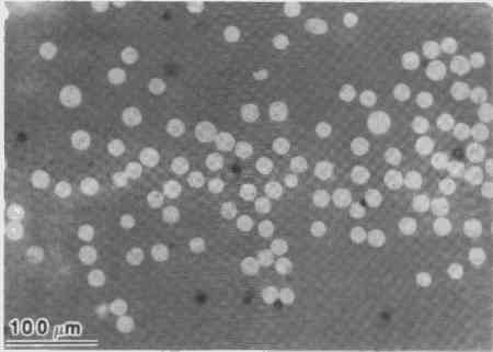
Fig. 2.13. An optical micrograph of a cross-section of a unidirectional alumina fiber/glass matrix composite made by slurry infiltration.
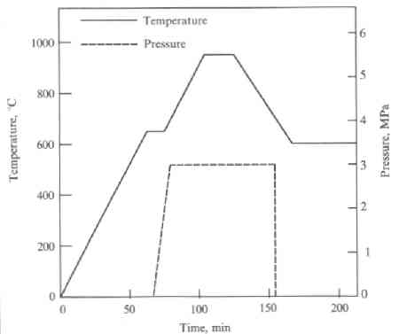
Fig. 2.14. The pressure and temperature schedule used during hot pressing of this composite.
Liquid Infiltration:
This technique is very similar to liquid polymer or liquid metal infiltration. Proper control of the fluidity of liquid matrix is very important.
It yields a high density matrix, i.e. no pores in the matrix.
Almost any reinforcement geometry can be used to produce a virtually flaw-free composite in a single processing step, with small dimensional change from preform to final product.
However the process is limited by fiber-damaging chemical interactions between the fibre and the matrix at the high temperatures required and by the high viscosities of molten ceramics and glasses.
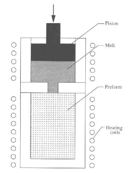
Fig. 2.15. A schematic of the melt infiltration process.
Some special versions of liquid infiltration techniques are as follows:
- High Pressure impregnation of Carbon
- Pressure Casting/squeeze Casting
- Pultrusion
- Directed Oxidation Process
High Pressure impregnation of Carbon
A special variant of the liquid infiltration method, often employed to fabricate carbon/carbon composites, is called high pressure impregnation of carbon (HPIC). A schematic of the HPIC method to fabricate C/C composites by liquid infiltration is presented below.

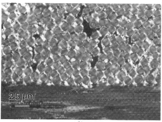
Fig. 2.16. (a) Schematic of a process for making carbpn/carbon composites by liquid infiltration; (b) a two-dimensional carbon/carbon composite made by liquid infiltration of a resin, followed by charring of resin to carbon (courtesy of K. Upadhya).
Pressure Casting/squeeze Casting
The infiltration of a fibrous preform by a molten intermetallic matrix material under pressure has been accomplished.
Alumina fiber reinforced intermetallic matrix composites using Fe3Al, Ni3Al, and TiAl as matrix materials have been fabricated by squeeze casting (or pressure casting).
The matrix material is melted in a crucible in a vacuum, and the fibrous preform is heated. The molten matrix alloy is poured to the fiber preform and solidify to form the composite.
Pultrusion
Another version of the liquid infiltration technique is the pultrusion of continuous fibers through moten glass; an example of fabricating SiC/Glass composites is shown below.
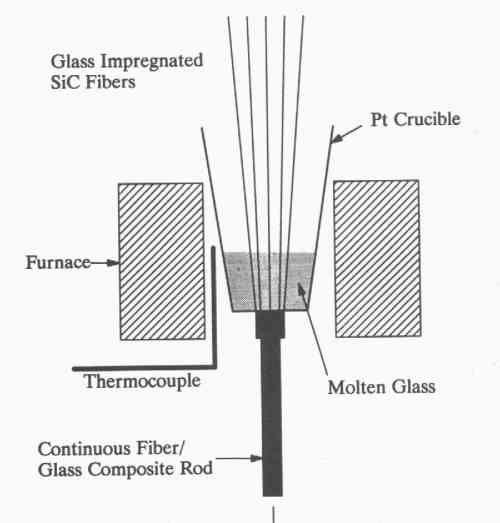
Fig. 2.17. The technique for making SiC/glass composite by the pultrusion of contiuous fibers through molten glass.
Directed Oxidation Process
Another variant of the liquid infiltration is the directed oxidation process or the Lanxide process, developed by Lanxide Corporation.
One of the Lanxide processes is called DIMOX, which stands for the directed metal oxidation process. The directed oxidation of Al to produce Al2O3 is shown below.

Fig. 2.18. DIMOXTM directed metal oxidation process (courtesy of Lanxide Corporation).
Chemical vapor infiltration, CVI:
In the CVI process, the desired matrix is chemically vapor deposited within a porous preform, which is often fibrous, to produce the composite material.
A schematic of the forced chemical vapor infiltration (FCVI) process is shown below .
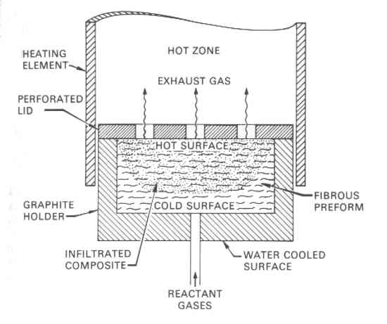
Fig. 2.19. A forced chemical vapor impregnation (FCVI) process combining thermal gradient and pressure gradient approaches (courtesy of R. Lowden, Oak Ridge National Laboratory).
Main advantages of the method are as follows:
Good mechanical properties at high temperatures.
Large, complex shapes can be produced in a near-net shape.
Considerable flexibility in the fiber and matrixes.
The main disadvantage of the method is that it is slow and expensive.
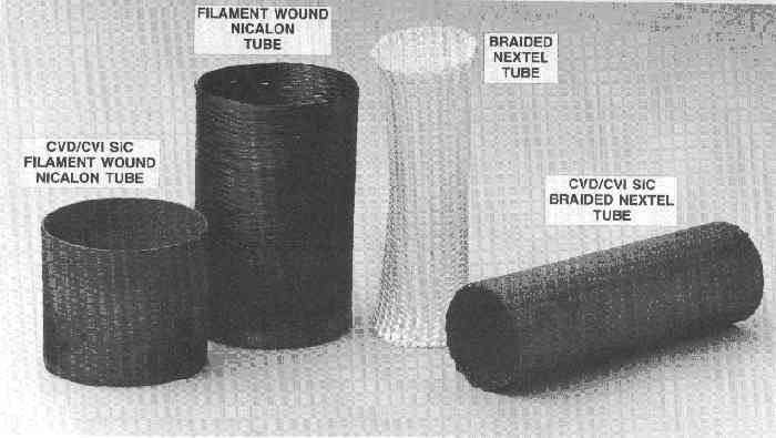
Fig. 2.20. A filament wound Nicalon tube and a braided Nextel tube before CVI and after CVI.
